Hopefully you found the discussion about the mechanical design of my MAME setup informative, but the thing that – for better or worse – sets this apart from most of the others on the internet is the fact that it uses a wireless keyboard for control. One could probably use a wireless game controller (or possibly two) with similar or better results.
The first thing to consider when using a wireless keyboard (or wired keyboard for that matter) for this purpose is how to imitate a keystroke with a button and joystick. At its core a button is simply a switch and a joystick is four switches. A key on a keyboard is a switch as well. Unfortunately it’s not as simple as just replacing the key switch with an arcade-style button.
The challenge with keyboards is that each key doesn’t go to one discreet input on the controller, instead there is an array of positive or signal connections and grounds that must be connected in a certain way to activate each keystroke. Unless you can get a spec sheet from Microsoft or Logitech you’ll have to figure out the combination for each key yourself. If you happen to be using the exact keyboard that I did (Microsoft Model: 1014 keyboard and 1028 receiver), I’ve provided a list of the keys at the end of this article that I mapped so there’s a small chance that this article could help you.
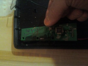
So how do you map the keys? The first step is to take the keyboard apart (obviously). Inside you’ll find 3 sheets of plastic. Two will have printed circuits on them where the third separating them will not. The way this works is that two sides have contacts separated by another thin sheet of plastic. When the key is pressed the signal and common sides are connected. There are a number of signal wires coming from the controller and a number of grounds (8 grounds and 16 signals in this case). If you connect them in the right combination it equals a letter, number, or symbol. If you look at the upper-left side of the keyboard sheets above you’ll see where the sheet connects to the wireless chip.
So what you will need to do is use a voltmeter to trace out the wires from the place the key would need to be to the place it connects to the main circuit board. Once you trace this out for the signal and commons, if you connect them together (with a button or joystick) that will give you a signal for the corresponding keystroke. That’s the basic idea, but there are some good tutorials on youtube if you need more insight. One thing to keep in mind is that if you’re trying to trace it with an audible signal, sometimes the connection isn’t that great and won’t give you a total short. Look a the display and this will show the poorer connections if you don’t hear the “beep.” Also, I wrote the actual letters on the plastic sheet from the keyboard and the numbers on the wireless PCB. This will probably help, and it’s not like you will need to use the keyboard again.
In order to hook everything up you’ll need to following parts:
- perf board line pattern – ecs-4 – $6.25 – allelectronics.com
- IDE cable – cbl-48 – $3.65 – allelectronics.com
- snappable headers 2×40 pin – dhs-40 – 1.25
- small (around 22 ga) wire from Radio shack – approx $5.00
- 2 AA battery holder from Radio shack – approx $2.00
- .24 inch black poly spot (100/sheet) – rf-52 – $2.00 allelectronics.com (for the bottom of the cabinet – technically mechanical but you don’t want to put in 2 orders)
- And of course you need the keyboard that this is all based off of
As for tools, you’ll need:
- Soldering iron and solder
- Voltmeter
- Cutting tool
- File or Dremel tool
- Vise
Once you get it all traced out (or actually before, it doesn’t really matter) solder each connection on the keyboard circuit board to an IDE 40 cable that you would use for a hard drive. The link listed before does a pretty good job of explaining it, but an old-style IDE 40 cable has 40 conductors as you’d expect. The newer IDE/ATA cables actually have 80 conductors, but every other one is linked to ground. This is what I used, but it’s somewhat of a pain because you’ll have to go through and separate out the ground wires which should be every other one.
The connection at the other end of the ribbon has two sides of which I used one for signal and one for ground. Every other signal goes to a different side of the connector in order and given that I was using an IDE/ATA cable this meant there was a ground in between every signal. Trace it out with your voltmeter, but the pattern that resulted was: ground, signal, ground, common, ground, signal, ground… on and on and on until you reach 80 wires. I separated each and marked the signal and grounds with red and blue markers so I didn’t get them mixed up. If you can get a true IDE 40 pin cable that would probably be much easier.

Attaching the board to a solid surface will help you solder it. I'm not sure that this is the correct way to hold your iron, however.
You’ll also need somewhere for the cable to connect to, so this is where the line pattern perf board and 2 x 40 snappable headers come in. Cut a piece big enough for the connect each lead to a pin as shown below, then file the connector in two so that each side is electrically isolated. Solder the header on as shown, snap the IDE cable on and you’ve got something to solder your button leads to.
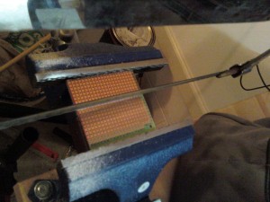
File the perf board as shown. Again, a vise is a good tool to use with this, also a Dremel Tool would work well.
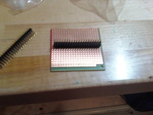
put the header (set of jumpers) on and solder. Jumpers should actually be on the other side to solder, but you can see the position here.
At this point you’ll also want to hook up a 2 AA battery pack to power it. You should go ahead and test your setup at this point. With voltage on you should be able to produce symbols and letters by attaching the appropriate signal and common together.
Once you’ve got this, the only thing left to do is test the keys that you have decided to use and solder them to the appropriate buttons. This is not an easy task and you may find that some “keys” don’t work the way you wanted them to. Don’t be too much of a perfectionist about this, it’s acceptable to do some experimentation and possibly skip some keys that don’t work as you expected.
Also, you may find that your soldering skills aren’t up to par or that you’ve just wasted quite a bit of time hacking together a controller that you could have bought for around $40. With my setup, I was only able to get the joystick working with 3 buttons and some of the buttons didn’t work together well. For simple games like Galaga or Pacman, this would work well, especially if you absolutely need it to be wireless (I haven’t found an encoder to buy that is wireless, but they may be available). However, in terms of time and how well it works, after doing this, I would say go with a purchased encoder.
If you really want to set up your system like I did, this is the way to do it. I’ll probably do another article sometime in the future where I convert it to use an encoder and make the cabinet presentable (maybe encoders aren’t that great, I haven’t tried using one yet).
As promised, here is a pinout on Microsoft wireless keyboard model 1014.


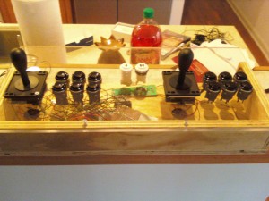
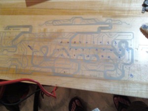


Pingback: MAME using an encoder |